Virtual Science Ltd
+44 1249 736656
Measuring the Speed of Water Waves
Introduction
A wave is an oscillation of something that transfers energy along its path of propagation without transferring any matter. Think of a wave produced by flicking the end of a long rope. A wave will travel along the rope, but no part of the rope is actually moving in the direction of the wave; the parts of the rope are simply going up and down.
If we tied the far end of the rope to a fixed point and oscillated the near end, we would set up a pattern of moving waves on the rope. This is a transverse wave, where the direction of the wave motion is at right angles to the disturbance, which is up and down. This is also like the wave motion in the sea, where the water is going up and down and a surfer can ride the crest of a wave and be propelled forward in the direction of propagation of the wave. The distance between successive crests is called the wavelength. The number of complete waves per second is called the frequency, measured in hertz (Hz). One Hz is one cycle (complete wave) per second. The wavelength is often represented by the Greek letter lambda (λ) and the frequency by v. As shown here, the horizontal axis is time.

The amplitude of the wave is also shown here as A. There is a simple relationship between the speed of the wave, its frequency, and its wavelength:
v = fλ
This is easiest to understand if you just consider the case where the frequency is one cycle per second. In this case, the wave must propagate exactly one wavelength each second.
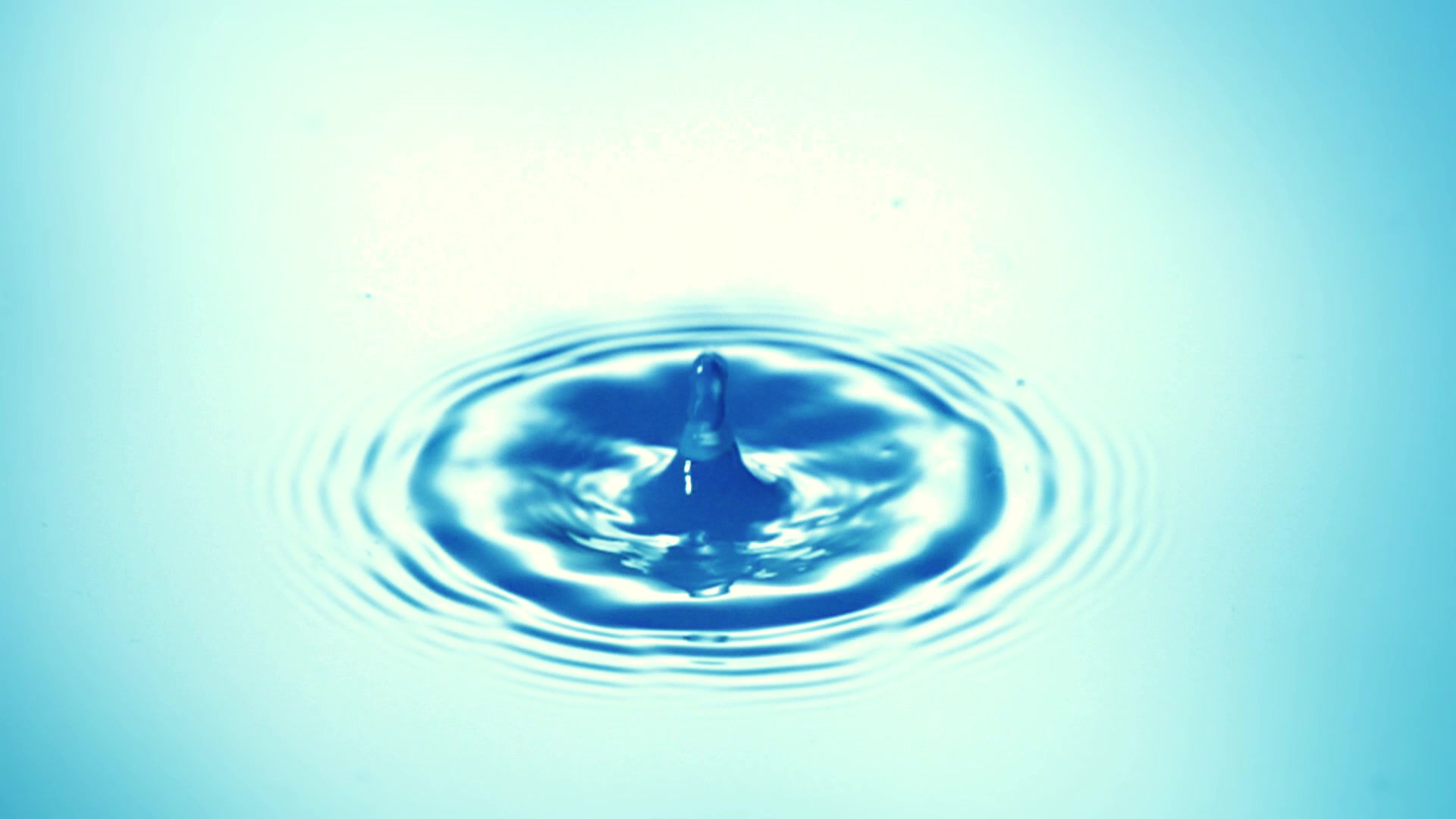
A water ripple is a wave that propagates in water. It is a vertical oscillation of the water. We’ve all seen rain falling onto the surface of a still pond or large puddle. Each raindrop that falls creates a circular wave that moves outwards from the point of contact of the raindrop and the pond. The wave crest travels outwards at constant speed. These waves are a little unusual as there is only one created for each wave, whereas most waves continuously emit crests; for example, the waves breaking onto a shore. In our experiment, we need a continuous supply of crests, and we can arrange this by using a plunger that disturbs the water at regular periods. Like the waves on a rope, this is an example of a transverse wave where the direction of the wave is at right angles to the disturbance, which is up and down.

The objective
To determine the speed of waves in water.
The apparatus
• A ripple tank
• An electrical plunger
• A signal generator
• A strobe light with frequency controller
• A white screen slightly wider than the length and width of the ripple tank
• A ruler
The signal generator should be connected to the plunger that just touches the water at full extension. The strobe should be placed above the ripple tank so that the shadow of the water waves is projected onto the screen.
The variables
The independent variable is the frequency of the waves, and the dependent variable is the speed of the waves.
The Physics
The important relationship is that between frequency, wavelength, and speed which is given by:
v = fλ
We will use this to calculate the speed of the wave, by observing the wavelength of the wave and the frequency as set on the generator.
The method
The basic idea is to set the plunger hitting the water with a given frequency, and then to match this on the strobe so that the projected wave appears to be stationary. This makes the wave’s length much easier to measure.
Switch the signal generator on and dim the room lights, which will make the waves’ shadows easier to see. Set the frequency to 2.00 Hz and set the strobe to the same. Measure the distance between two crests and record your results in the first row of this table:

Repeat the same process for all the frequencies given in the table and record your results.
The Video
Watch a video of the Speed of Water Waves e-practical here.
This shows how to use it and how to collect the data.
The e-Practical
Perform the experiment yourself, collect your own data, make mistakes and be able to correct them. The e-practical requires that your browser canrun WebGL 2 (usually found on Windows browsers, safari on iOS, and various Mobile browsers, test with https://get.webgl.org/webgl2/). This link is for students and evaluation only, schools should purchase a site licence.
The e-practical will run on laptops and desktops for PCs and Apple computers and will run on mid to high spec tablets and 'phones. All the e-practicals will run on devices as small as a mobile 'phone. However, the best experience is on a PC using a mouse which gives very precise control, but if you are limited to a small device, consider using a stylus or a blue tooth mouse.
On a portable device, make sure you click on 'Toggle onscreen controls'. The left joystick controls movement, the right joystick controls direction and where you are looking.
Lower the lights in the room using the light switch. You can draw the blinds using the switch on the wall beneath the window. Switch on the frequency generator using the red button. Use the scroll wheel on the knob marked ‘Frequency’ to change the frequency of the plunger. Match the frequency on the strobe using the red knob on the strobe.
Position yourself in a good place to see the wave shadows and the ruler. You will almost certainly need to zoom in (use plus and minus on the keyboard or the Z and X keys. If you are using on-screen controls, then there are magnifying icons on the screen that you can click on). You may need to adjust the light level so that you can see the wave shadows and the ruler markings at the same time.
The Results
You can use the formula:
v = fλ
To calculate the velocity of the wave at each frequency, these should all be approximately the same. You should plot the frequency on the Y-axis and one over wavelength on the X-axis for all the results. You should get a straight line where the gradient is the required velocity.
Further Discussion
There is a problem with the experiment in that the ruler is calibrated correctly in centimeters, but the wave shadow is in fact an enlargement due to the projection by the strobe light. You should be able to think of several different ways of adjusting for this. Try to think of a physical way of adding to the apparatus so that the distance can be measured accurately. How would you compensate for the enlargement by using geometry alone?
Note: There is a ruler at the back of the apparatus that should help you get the values you need for the geometric adjustment to be made.
Exam Questions
AQA June 25 Foundation Paper 2

Be careful, if you are not sure, the answer can be found in the introduction.

If you are not sure, the answer can be found in the introduction.

A simple bit of Maths and getting the right units gets you 3 marks! A clue to the correct units is in the question. You are asked for a length, only one of the given units is a length!

A simple bit of division gets you two more!
This section is adapted from material developed by Dr Robert Lucas and is related to the book High School and Undergraduate Physics Practicals, published by CRC Press.