
Virtual Science Ltd
+44 1249 736656
IV Characteristics of an LED
Introduction
This experiment plots the IV characteristics of a diode; that is, you plot how the current changes when you change the voltage (the I is for current, and the V is for voltage). Diodes have the property that they essentially only let current flow in one direction. Most diodes are semiconductor diodes that consist of some semiconductor material with two terminals or connections. Karl Ferdinand Braun discovered the first solid-state semiconductor in 1897 and recognized its use as a rectifier for alternating current (AC). He was also an early pioneer of using these crystals, as they were called, to detect radio waves. The crystal radio sets would have a simple coil and variable condenser for tuning into a particular radio frequency. The signal from this would simply be passed in series through a crystal that would cut out the negative part, allowing the subsequent signal to drive a headphone. Without the crystal diode, the positive and the negative parts of the original signal would cancel each other out. The crystal diode in these early sets would simply consist of the mineral part held rigidly in a holder, and a gold wire, called the cat’s whisker, which could be adjusted to make a good contact with the mineral. This is the circuit for a crystal set capable of receiving strong amplitude modulation (AM) signals. Note that the tuning part of the circuit consists of a coil and a variable capacitor connected in parallel. This picks out the frequency you want to tune to, and then the diode rectifies the signal from that frequency so you can hear it.

The light-emitting variety of diode was first created by Oleg Losev in 1927 and has found many applications, not least of which is low-energy lighting. The reason it is low energy is that we get most of the electrical energy converted to light with very little heat produced.
The objective
To plot the relationship between the current and the voltage for a diode and establish that a diode only conducts in one direction.
The apparatus
You will need:
-
A DC power supply
-
Two multimeters
-
A breadboard;
-
An LED
-
A 4.7k ohm variable resistor
-
A 330 ohm resistor

The circuit
The circuit for measuring IV characteristics for any device is mostly the same. A power source is connected in series with a variable resistor, an ammeter, and the device being tested. A voltmeter is connected across the device, which in this case is the LED.

However, for the LED, we are going to modify this circuit to protect the diode from being damaged by too high a current, note the addition of a 330 Ohm resistor.

The variables
The independent variable is the voltage, and the dependent variable is the current. You are effectively controlling the voltage across the diode with the potentiometer.
The method
Switch on the power. With the power on, you now need to vary the resistance of the variable resistor (sometimes called a potentiometer or even just a pot); this will change the current flowing through the device.
Take readings at every 0.1 volt. Note that the right-hand meter in the e-practical is set to display microamps. To get readings for negative voltages, either reverse the polarity of the power supply or unplug the LED and reconnect it so that its connections are reversed.
In the e-practical you can switch on the power supply by clicking on the red on/off button. You should see the Output indicator on the power supply screen indicate a connection,
The variable resistor can be varied by placing the mouse cursor over the knob and using the mouse wheel or by jdragging if using the on-screen controls.
To get readings for negative voltage, switch off the power and click on the LED; this will reverse its connections in the circuit. Now turn the power on and repeat the readings taken previously. The voltages this time count as negative, as the LED is now connected the other way around.
The Video
Watch a video of the IV Characteristics e-practical here.
This shows how to use it and how to collect the data.
The E-Practical
Perform the experiment yourself, collect your own data, make mistakes and be able to correct them. The e-practical requires that your browser canrun WebGL 2 (usually found on Windows browsers, safari on iOS, and various Mobile browsers, test with https://get.webgl.org/webgl2/). This link is for students and evaluation only, schools should purchase a site licence.
The e-practical will run on laptops and desktops for PCs and Apple computers and will run on mid to high spec tablets and 'phones. All the e-practicals will run on devices as small as a mobile 'phone. However, the best experience is on a PC using a mouse which gives very precise control, but if you are limited to a small device, consider using a stylus or a blue tooth mouse.
On a portable device, make sure you click on 'Toggle onscreen controls'. The left joystick controls movement, the right joystick controls direction and where you are looking.
The Results
Plot a graph of current in amps on the Y-axis and volts on the X-axis for the entire range of voltage readings. You should see an L-shaped plot with the current zero through all negative values until the diode switches on at some positive value.

Further Discussion
Find a specification sheet online for an LED. How closely does your graph compare to the specification?
Exam Questions
AQA May 25 Foundation Paper 1


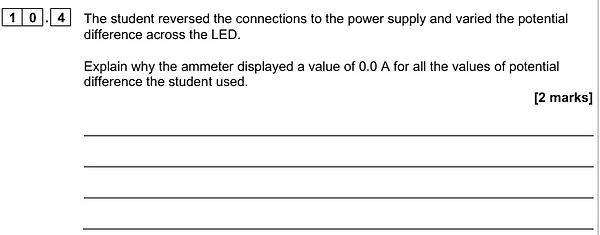
If this confuses you, read the first few sections above and make sure to do the e-practical.
AQA May 24 Foundation Paper 1

You should recognize this as the standard setup and circuit for an IV investigation. You can base your description on the standard IV investigation but as this is going to investigate the change in resistance against the wire length, it is not the voltage that needs to change, but the length of the wire in the circuit determined by the placement of the rightmost crocodile clip.
The e-practical 'Resistivity of Constantan' despite being an A level required practical, is a very good fit for this question, you might like to try it. It is a simple experiment that corresponds perfectly with the picture given in the first part of the question.

The more wire you have in the circuit then the more resistance. This is a linear relationship, double the length of the wire and you double the resistance. Only one of the graphs shows this relationship.

The answer is in the question, it has only a potential difference of 1.5V, a battery voltage we use around the house for torches, radios, and many other devices.
This section is adapted from material developed by Dr Robert Lucas and is related to the book High School and Undergraduate Physics Practicals, published by CRC Press.