
Virtual Science Ltd
+44 1249 736656
Resistors in series and parallel
Introduction
Resistors impede the flow of current in a circuit. We use them in electrical and electronic circuits to control the flow of current. The higher the resistance, the less current that flows. However, there are two different ways we can connect resistors together, either in series or in parallel. This experiment will allow you to investigate the combined resistance of resistors connected both ways.
Resistance is measured in ohms, the symbol for which is the Greek letter omega, Ω. The unit is named after Georg Simon Ohm, who was a German physicist and mathematician. He discovered that there is a direct relationship between potential difference across a conductor and the amount of current that flows. This is known as Ohm’s law.
The objective
To investigate the combined resistance of resistors in series and in parallel and to confirm the rules for calculating the combined resistance of resistors in series and parallel.

The apparatus
-
A breadboard
-
A battery
-
Some resistors of the same and different values
-
Some electrical wire
-
A multimeter or an ammeter
The breadboard needs to be wired as shown below and connected to the battery and ammeter as shown above.

The variables
The current is the dependent variable, and the independent variables are the resistors used in the circuit.
The Physics
Ohm’s law gives us the means of calculating the voltage given the current and resistance in a simple circuit.
The law is:
E = IR
Where E is the electromotive force (potential difference or voltage) in volts, I is the current in amps, and R is the resistance in ohms. The equation can be rearranged to give us any one of the three factors, given the other two.
Resistors in series like that shown here have a combined resistance of the sum of their individual resistances. In this case:
R = R1 + R2

The combined value can then be used in Ohm’s law to calculate either the voltage or the current, given that one of them is known. But note that if the voltage and current are known, as would be the case in the previously described circuit, then only the combined resistance can be calculated.
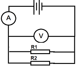
For resistors in parallel, as shown here, the combined resistance is given by the equation:
1/R = 1/R1 + 1/R2 + . . .
These two laws for calculating the total resistance of resistors in series and in parallel are what you are going to verify in this experiment.
The method
The breadboard configuration allows for row 1 to be used for a single resistor, row 3 for two resistors in series, row 5 for three resistors in series, row 7 for a second resistor in parallel (with row 1), row 9 for three resistors in parallel, and row 11 for four resistors in parallel.
The breadboard contacts should be wired in series with the ammeter (or multimeter measuring current) and the battery.
Resistors should now be placed into the breadboard to give configurations for resistors in series and parallel.
For the initial investigation, you should use resistors of the same value. There are three 33 ohm resistors at the nearest end of the cork mat; they are colored orange, orange, black (orange is for 3 and black is for 1, which is the multiplier). This is how we identify the value of a resistor. Resistors have preferred values, so only some combinations are used. You can look up a resistor color code chart online or use the one inside the e-practical.
The multimeter will read the current for the circuit, whatever the configuration.
Using only the 33 ohm resistors, place one on row 1 where the yellow strip is. Record the current and calculate the resistance of the resistor using the assumed voltage of the battery and the current reading. Return the resistor to the cork mat. Now place two of the 33 ohm resistors in series on row 3 of the breadboard, record the current and calculate the combined resistance from it. Return the two resistors to the cork mat. Now place three of the 33 ohm resistors onto row 5 of the breadboard. Again, calculate their combined resistance from the recorded current.
The Results
For resistors connected in series, you should be able to verify that the total resistance in each case is the sum of the individual resistances.
For resistors connected in parallel, you need to confirm the more complicated formula.
1/R = 1/R1 + 1/R2 + . . .
The Video
Watch a video of the Resistors in Series and Parallel e-practical here.
This shows how to use it and how to collect the data.
The E-Practical
Perform the experiment yourself, collect your own data, make mistakes and be able to correct them. The e-practical requires that your browser canrun WebGL 2 (usually found on Windows browsers, safari on iOS, and various Mobile browsers, test with https://get.webgl.org/webgl2/). This link is for students and evaluation only, schools should purchase a site licence.
The e-practical will run on laptops and desktops for PCs and Apple computers and will run on mid to high spec tablets and 'phones. All the e-practicals will run on devices as small as a mobile 'phone. However, the best experience is on a PC using a mouse which gives very precise control, but if you are limited to a small device, consider using a stylus or a blue tooth mouse.
On a portable device, make sure you click on 'Toggle onscreen controls'. The left joystick controls movement, the right joystick controls direction and where you are looking.
Click on a resistor and then click on the breadboard for where you want the resistor to be placed.
You can return a resistor to the cork mat by clicking on it while it is positioned on the breadboard.
The multimeter will read the current for the circuit, whatever the configuration.
Using only the 33 ohm resistors, place one on row 1 where the yellow strip is. Record the current and calculate the resistance of the resistor using the assumed voltage of the battery and the current reading. Return the resistor to the cork mat. Now place two of the 33 ohm resistors in series on row 3 of the breadboard, record the current and calculate the combined resistance from it. Return the two resistors to the cork mat. Now place three of the 33 ohm resistors onto row 5 of the breadboard. Again, calculate their combined resistance from the recorded current.
Further Discussion
Can you confirm the two laws using a mixture of resistance values?
What happens when you mix resistors in parallel with resistors in series?
This section is adapted from material developed by Dr Robert Lucas and is related to the book High School and Undergraduate Physics Practicals, published by CRC Press.