
Virtual Science Ltd
+44 1249 736656
Diffraction Using a Monochromatic Laser
Introduction
Light behaves as a wave in this scenario and as such, it is capable of interference in much the same way as water waves can interfere. Peaks and troughs cancel each other, two peaks make a bigger peak, and two troughs make a deeper trough. In particular, if light is passed through a grating, there will be a pattern of constructive and destructive interference. It is that pattern from a grating, where we know the number of lines per millimeter, that is going to be measured in this experiment to determine the wavelength of the light emitted by the laser. Once this has been found, we can then determine the number of lines per millimeter for a different grating as an additional exercise.
The objective
To determine the wavelength of the laser and, once this has been found, to determine the number of lines per millimeter for a different grating.
The apparatus
-
A laser source – a cheap laser pointer is ideal
-
Two 1.2-meter or longer rulers
-
Two diffraction slides with different line spacings
-
Wooden mounts for the ruler, slides, and laser
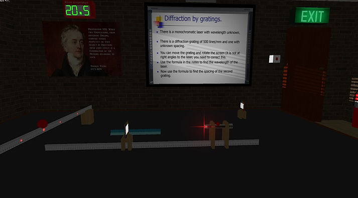
Configure the apparatus as indicated below. Lasers should be handled with great care. Never point a laser light at another person or randomly. Always know where the light is going before switching it on. Users should be aware of official safety advice such as that available from Consortium of Local Education Authorities for the Provision of Science Services (CLEAPSS).
The variables
The independent variable is the distance from the grating to the screen (which is also the ruler). The dependent variable is the distance from the zero order to the second order maximum.
The Physics
Consider the figure below, which shows light from two different slits in the grating arriving at the same spot on the screen, where the grating and the screen are at a distance of L and the slits are a distance d apart.

In the diagram we see the paths of two light rays starting a distance of d apart. As d is very much smaller than L, we can consider that the beams are for all intents and purposes parallel, which means that the difference in length is dsin(Ɵ) (from the small right-angled triangle with hypotenuse d). For the wave from each of these rays to constructively interfere, they need to be an exact multiple of a wavelength apart. So we can write:
dsin(Ɵm) = mλ (equation 1)
Where m is the number of the order. In the diagram, the bright spot in the middle is the zero order maximum, the two to either side are the first order maxima, the next two are the second order maxima, and so on.
We can denote the distance from the zero order maximum to the mth order maximum as ym. From the diagram, using the big triangle with base L:
sin(Ɵm) = ym/√(L² + ym²)
Remember that the sine of an angle is the opposite over the hypotenuse of a right-angled triangle. We have calculated the hypotenuse using Pythagoras’s theorem.
If we now substitute this into equation 1, we get:
dym/√(L² + ym²) = mλ
or:
λ = (d/m)ym/√(L² + ym²) (equation 2)
You should use the second order (m = 2) and obtain the readings for L and y2. You can calculate d from what is written on the grating.

Question: What is the highest order maximum visible in the screenshot?
The method
Switch the laser on and switch off the room lights, which will make the diffraction order maxima much easier to see.
Rotate the screen ruler so that the second order maxima are at an equal distance from the zero order maximum. This makes sure that the screen ruler is perpendicular to the laser light source.
Adjust the position of the grating so that the orders are well spread out along the ruler, which is acting as a screen.
Take measurements of the distance between the grating and the screen, L, and then between the zero order and the second order maximum using the screen ruler.
The Video
Watch a video of the Diffraction e-practical here.
This shows how to use it and how to collect the data.
The e-Practical
Perform the experiment yourself, collect your own data, make mistakes and be able to correct them. The e-practical requires that your browser can run WebGL 2 (usually found on Windows browsers, safari on iOS, and various Mobile browsers, test with https://get.webgl.org/webgl2/). This link is for students and evaluation only, schools should purchase a site licence.
All the e-practicals will run on devices as small as a mobile 'phone. However, the best experience is on a PC using a mouse which gives very precise control, but if you are limited to a small device, consider using a stylus or a blue tooth mouse.
The ruler on the left is initially not quite at right angles to the zero order light beam, and you will need to rotate it into perfect alignment by using the mouse wheel when the cursor is over the central red knob.
You can switch the laser on using the red knob on the top.
You can switch off the room lights using the switch by the door.
The grating originally on the ruler is marked with the number of lines per millimeter. You will need this for your calculation.
The central grating can be moved along the ruler by placing the mouse cursor over it and using the mouse wheel. The exact position of the grating can be determined from the pointer, as shown below.

You can zoom in and out using the plus and minus or Z and X keys on the numeric pad or the magnify icons when using the onscreen controls.
Clicking on the other grating, which is to the back and right of the table, will swap it with the 500 lines per millimeter grating. The laser needs to be off for the swap to occur.
The Results
Using equation 2:
λ = (d/m)ym/√(L² + ym²)
Substitute your values for L and y2. You can determine d from what is written on the grating.
Further Discussion
Now that you know the wavelength, you can calculate the slit spacing of any other grating.
With a different grating of unknown spacing in position, measure the distance to the furthest order maximum you can see. We can rearrange equation 2 to allow us to calculate d:
d = mλ√(L² + ym² ) /ym
When you have the spacing, you need to use it to calculate how many lines per millimeter, which is given by:
Lines per mm = 0.001/d
This section is adapted from material developed by Dr Robert Lucas and is related to the book High School and Undergraduate Physics Practicals, published by CRC Press.